555 Timer Schematic - Ecen 2250 Mydaq Experiment 1 Capacitors And The 555 Timer - Electronics tutorial about the 555 timer and how the 555 timer can be used as a 555 monostable or 555 bistable timer to generate timing pulses.
555 Timer Schematic - Ecen 2250 Mydaq Experiment 1 Capacitors And The 555 Timer - Electronics tutorial about the 555 timer and how the 555 timer can be used as a 555 monostable or 555 bistable timer to generate timing pulses.. In the mwe, two tikz objects are created that can be placed and identified as the components in schematic editors such as proteus or eagle, pins will be identified by coordinate names using the macro coordinate; But it has a lot of other interesting applications too. When vcc > 9v, the base to emitter junction starts to zener and. The 555 timer is a chip that can be us… Electronics tutorial about the 555 timer and how the 555 timer can be used as a 555 monostable or 555 bistable timer to generate timing pulses.
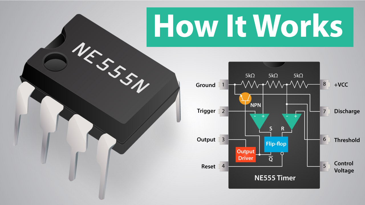
In this tutorial we will learn how the 555 timer works, one of the most popular and widely used ics of all time. In the mwe, two tikz objects are created that can be placed and identified as the components in schematic editors such as proteus or eagle, pins will be identified by coordinate names using the macro coordinate; The schematic shows (3) circuits, because one circuit does not work well over the entire vcc range. The 555 timer is a commonly used ic designed to produce a variety of output waveforms with the addition of an external rc network. Learn about the 555 timer and how it works in astable mode.
555 Timer Ic Working Principle Block Diagram Circuit Schematics from howtomechatronics.com It's a simple source of oscillating current that can power blinking leds, generate tones, and lots of other useful many times when you see a project with flashing leds, it's a 555 timer at work. The 555 timer, designed by hans camenzind in 1971. D timing from microseconds to hours d astable or monostable operation d adjustable duty cycle. The schematic shows (3) circuits, because one circuit does not work well over the entire vcc range. The 555 timer is an integrated circuit, it is extremely versatile and can be used to build lots of different circuits. The 555 timer is a commonly used ic designed to produce a variety of output waveforms with the addition of an external rc network. Electronics tutorial about the 555 timer and how the 555 timer can be used as a 555 monostable or 555 bistable timer to generate timing pulses. With over 80 different electronic circuits that you can build.
Derivatives provide two (556) or four (558) timing circuits in one package.
The 555 timer is an integrated circuit, it is extremely versatile and can be used to build lots of different circuits. The first simply uses a normal 2n3904 garden variety transistor, and this works well when vcc < 9v. You can watch the following video or read the written tutorial below. The 555 timer is a chip that can be us… D timing from microseconds to hours d astable or monostable operation d adjustable duty cycle. Electronics tutorial about the 555 timer and how the 555 timer can be used as a 555 monostable or 555 bistable timer to generate timing pulses. When vcc > 9v, the base to emitter junction starts to zener and. All the electronics info you need to know about the 555 timer. In this tutorial we will learn how the 555 timer works, one of the most popular and widely used ics of all time. This article covers every basic aspect of 555 timer ic. The schematic shows (3) circuits, because one circuit does not work well over the entire vcc range. Learn about the 555 timer and how it works in astable mode. The 555 timer ic is an integrated circuit (chip) used in a variety of timer, delay, pulse generation, and oscillator applications.
In the mwe, two tikz objects are created that can be placed and identified as the components in schematic editors such as proteus or eagle, pins will be identified by coordinate names using the macro coordinate; The 555 timer is a commonly used ic designed to produce a variety of output waveforms with the addition of an external rc network. But it has a lot of other interesting applications too. It's a simple source of oscillating current that can power blinking leds, generate tones, and lots of other useful many times when you see a project with flashing leds, it's a 555 timer at work. Ne555, sa555, se555 precision timers.
A 555 Timer Ic Tutorial from groups.ist.utl.pt Electronics tutorial about the 555 timer and how the 555 timer can be used as a 555 monostable or 555 bistable timer to generate timing pulses. The 555 timer, designed by hans camenzind in 1971. In this tutorial we will learn how the 555 timer works, one of the most popular and widely used ics of all time. This tutorial provides sample circuits to set up a 555 timer in monostable, astable, and bistable modes as well as an in depth discussion of how the 555 timer works and how to choose components to use with it. The schematic shows (3) circuits, because one circuit does not work well over the entire vcc range. When vcc > 9v, the base to emitter junction starts to zener and. With this information you will learn how how the 555 works and will have. With over 80 different electronic circuits that you can build.
Ne555, sa555, se555 precision timers.
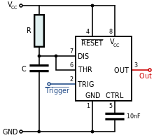
The 555 timer is a chip that can be us… On all other products, production processing does not necessarily include testing of all parameters. For the drawing of circuits, i use the structure according to the circuitikz manual. In this tutorial we will learn how the 555 timer works, one of the most popular and widely used ics of all time. All the electronics info you need to know about the 555 timer. This article covers every basic aspect of 555 timer ic. When vcc > 9v, the base to emitter junction starts to zener and. The 555 timer is a simple integrated circuit that can be used to make many different electronic circuits. The 555 timer is an integrated circuit, it is extremely versatile and can be used to build lots of different circuits. The 555 timer ic is an integrated circuit (chip) used in a variety of timer, delay, pulse generation, and oscillator applications. You can either follow the previous schematic or follow the breadboard wiring diagram below. Ne555, sa555, se555 precision timers. The schematic shows (3) circuits, because one circuit does not work well over the entire vcc range.
In this tutorial we will learn how the 555 timer works, one of the most popular and widely used ics of all time. On all other products, production processing does not necessarily include testing of all parameters. You can watch the following video or read the written tutorial below. In the mwe, two tikz objects are created that can be placed and identified as the components in schematic editors such as proteus or eagle, pins will be identified by coordinate names using the macro coordinate; (1) for all available packages, see the orderable addendum at the end of the datasheet.
555 Timer Ic Wikipedia from upload.wikimedia.org With over 80 different electronic circuits that you can build. And now a full schematic of the 555 timer oscillator with single step and free run option. The 555 timer is a commonly used ic designed to produce a variety of output waveforms with the addition of an external rc network. But it has a lot of other interesting applications too. For the drawing of circuits, i use the structure according to the circuitikz manual. If you still need a detailed understanding of the 555 timer. When vcc > 9v, the base to emitter junction starts to zener and. This tutorial provides sample circuits to set up a 555 timer in monostable, astable, and bistable modes as well as an in depth discussion of how the 555 timer works and how to choose components to use with it.
The 555 timer is an integrated circuit, it is extremely versatile and can be used to build lots of different circuits.
With this information you will learn how how the 555 works and will have. For the drawing of circuits, i use the structure according to the circuitikz manual. This tutorial provides sample circuits to set up a 555 timer in monostable, astable, and bistable modes as well as an in depth discussion of how the 555 timer works and how to choose components to use with it. Derivatives provide two (556) or four (558) timing circuits in one package. With over 80 different electronic circuits that you can build. Learn about the 555 timer and how it works in astable mode. All the electronics info you need to know about the 555 timer. You can watch the following video or read the written tutorial below. The first simply uses a normal 2n3904 garden variety transistor, and this works well when vcc < 9v. The 555 timer ic is an integrated circuit (chip) used in a variety of timer, delay, pulse generation, and oscillator applications. This article covers every basic aspect of 555 timer ic. You can either follow the previous schematic or follow the breadboard wiring diagram below. (1) for all available packages, see the orderable addendum at the end of the datasheet.


0 Komentar